
Designing a roof requiring tapered insulation is beset with challenges, with consequences for the contractor and specifier. Andrew Rowley, tapered design manager for Gradient Roofing, explains.
Designing tapered insulation for a flat roof used to be relatively simple. The Building Regulations offered a defined target that the roof (among other building elements) needed to achieve. The only debate was whether to meet that target based on the minimum depth of the tapered insulation or to set the tapered thicknesses so as to average the performance over the whole roof.
That might sound like a straightforward choice but it belies how long-standing the debate was – and how confusing specifications eventually became due to uncertainty over which method to work with.
The calculation of U-values is defined by an international standard – BS EN ISO 6946 – and in 1997 it included for the first time guidance on how tapered insulation should be calculated. The annex containing this guidance has become synonymous with the calculations issued to demonstrate the U-values – they are known as Annex C calculations.
Across England, Wales and Scotland the Building Regulations relating to energy use and thermal performance take a holistic view of the whole building.
U-value targets for floors, walls and roofs are just one part of the overall picture, and that picture is flexible, allowing freedom in design and specification subject to meeting a set of minimum criteria.
The required U-value performance is determined by SAP (Standard Assessment Procedure) calculations for domestic properties and SBEM (Simplified Building Energy Model) calculations for non-domestic buildings. It is possible to accept trade-offs in performance, where one building element can achieve lower U-values to compensate for another that might be constrained.
It is critical to ensure the building design and specified U-values can be achieved on site, otherwise the finished building will suffer a shortfall in performance. While Annex C calculations for tapered roofs have improved clarity for the insulation designers, they are less easy to understand for specifiers, contractors and some suppliers – and that can be an issue in itself.
So what is Annex C exactly? Most insulation in a building is specified at a uniform thickness. In the particular construction where it is being used, it therefore achieves a consistent U-value throughout. So it stands to reason that where tapered insulation is used the U-value will vary as the thickness varies.
While it may sound simple to take this into account, for an accurate calculation it is necessary to account for the roof pitch and length of fall as well as the minimum thickness of insulation. Consider a basic rectangular roof, with a 0.18 W/m2K U-value target and a 1:60 fall required across the width of the roof:
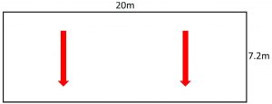
If the fall was to be created using firrings (or a similar method) then the required thickness of flat, tissue-faced board is straightforward to establish: 130mm.
A calculation for average thickness would result in a tapered range of 70mm to 190mm. The Annex C calculation works out that the thickness range should, in fact, be 80mm to 200mm.
This may seem close enough but bear in mind it is the simplest of roof designs. And even the smallest discrepancy from the designed thermal performance could result in the as-built SAP or SBEM calculations failing to meet the regulations, and costly remedial measures being required at the end of the build.
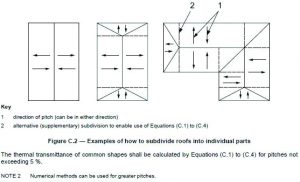
In addition, most roofs are more complex than a basic rectangle, featuring hips and valleys and varying lengths of falls. For an Annex C calculation, the roof design has to be broken down into a series of rectangular tapers, flat rectangles and triangles (both thinnest and thickest at apex).
The more elaborate the roof layout, the more laborious the tapered insulation design becomes, and the more time- consuming the calculations become – even in appropriate calculation software. The excerpts from BS EN ISO 6946 illustrate how roofs should be broken down.
The considerations don’t stop there either. Thought must be given to the position of rainwater outlets and whether the gutters will be flat or recessed. Table 2 illustrates the effect of different gutter designs on the tapered insulation for a simple roof.
![]()
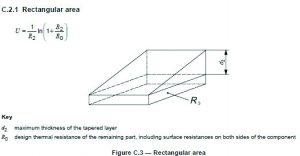
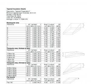
When all of the constituent pieces and shapes are accounted for, a definitive Annex C calculation can be provided to demonstrate compliance as part of the overall building design. The excerpt on the right illustrates a typical example:
So with calculations this complex, how can specifiers and contractors hope to understand whether a tapered insulation scheme complies with the U-value target established for a project? And where does any liability for non-compliance rest?
Tapered insulation designers can only interpret the scheme and specification given to them, highlighting the need for good communication and collaboration throughout the design and construction process – and as early as possible in that process.
Conscientious manufacturers support the scheme for competent U-value calculations that is administered by the BBA. Although Annex C calculations do not currently form part of the scheme, it is no less important that designers preparing calculations have a good grounding in basic calculation principles and be considered competent.
It may not be possible to go back to the days of simple roof calculations, as evidenced by the many schemes in the market that may not comply with Annex C, but we can help to ensure that the construction of complex, correctly-calculated roofs is as simple and painless as possible.